|
|||||||||
How GPR WorksSurface and Ground Penetrating Radar is a well established non-destructive method of investigating the internal composition of many naturally occurring materials such as rocks, earth and gravels as well as man made materials like brick, concrete and asphalt, etc.. It can be used to detect metallic and non-metallic pipes, sewers, cables, cable ducts, voids, foundations, reinforcing in concrete and a whole host of other buried objects. It is also used to investigate the depth and make up of different strata layers. A common use has been to scan areas of land before excavation takes place.Principle of OperationThe radar system sends out pulses of electromagnetic of EM energy and works by detecting the electrical echo caused when the pulse meets electromagnetic discontinuities, such as a pipe or void, within non-metallic structures and materials. By moving the radar across the surface an image is created similar to that of a CT scan. The measured profile is termed a “time profile” The depth is expressed in terms of Two Way Travel Time (TWTT) rather than true depth. TWTT is the time taken for the signal to leave the antenna transmitter, bounce off the target and the reflected energy to return to the antenna receiver. The longer the time window over which the radar observes the reflected signal, the further the signal will have traveled. Our system has a time window that can be adjusted in steps from 6 nanoseconds (ns) to 800 ns. Generally the operator will be using the equipment in the range of 26 to 50 ns.In the case of the 500 MHz antenna the radar sends out 1ns long pulses at a repetition rate of 1 MHz. The Fourier transform of this pulse is approximately a sinx/x or sine cardinal function and so in effect the spectrum of the energy is spread over a wide band of frequencies. One feature of our equipment is its ability to use a variety antennas centered on different frequencies for a wide range of applications. The center frequency of an antenna is a measure of the center of the range of frequencies to which the antenna is sensitive. With a standard antenna centered on 500 MHz typical penetration depths of around two meters are obtained in the most common occurring ground conditions and materials with a corresponding resolution of typically 5 cm. A 1GHz antenna will resolve targets to a higher degree of resolution, less than 1cm, but the penetration is also reduced to typically less than 75cm. Why not plot true depthA radar wave travels at different rates through different ground materials due to their differing EM Properties. Therefore, in order to be able to plot the profile as a true depth section, some method must be found which enables the speed of the propagation of the radar signal to be determined. If the ground simply consisted of a uniform media with isolated targets buried within it, the depth could be calibrated fairly accurately.The depth of penetration and the resolution of the measurements depend on a number of factors. Different types of ground behave very differently. Sand, loam, chalk, sand stone, Granite, etc. are all easy to penetrate and the radar can also be used to see through fresh water and snow. Cured concrete and other hard layers can be penetrated depending on the number and spacing of any reinforcing rods present. Soils which have a high percentage of dissolved salts and wet clay are the most difficult to work with. The Radar Wave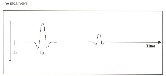 Time zero is a fixed point as far as the radar is concerned. The time the Tx Rx leakage pulse is detected depends on the separation of the two antennas. In our 500 MHz antenna the distance between the transmit ( Tx) and receive ( Rx) antenna is approximately 215mm. It will be the first event the radar detects. No real information will be seen before this. The only time To and Tp will coincide is when the Tx and Rx antennas occupy the same point in space. In reality this will never happen so Tp will always occur slightly after To. The following graph illustrates the effect that varying the separation of the two antennas has on the various timings.

|
800.565.3347
Why Choose Worksmart?
Find out why Worksmart is #1 in Subsurface Imaging >
Quick Links
Donate
Help find missing persons by donating to the Broken Wings Network |
||||||||
|
HOME | SITE MAP | EQUIPMENT | APPLICATIONS | REFERENCES | REQUEST A QUOTE
Contact us at (800) 565-3347 Copyright 2012 Worksmart, Inc. All Rights Reserved |
|||||||||